A great board to have if you need to expand the analog pins you’re using. This 8-channel analog multiplexer lets you read up to 8 analog sensors using just one analog input pin on your microcontroller.
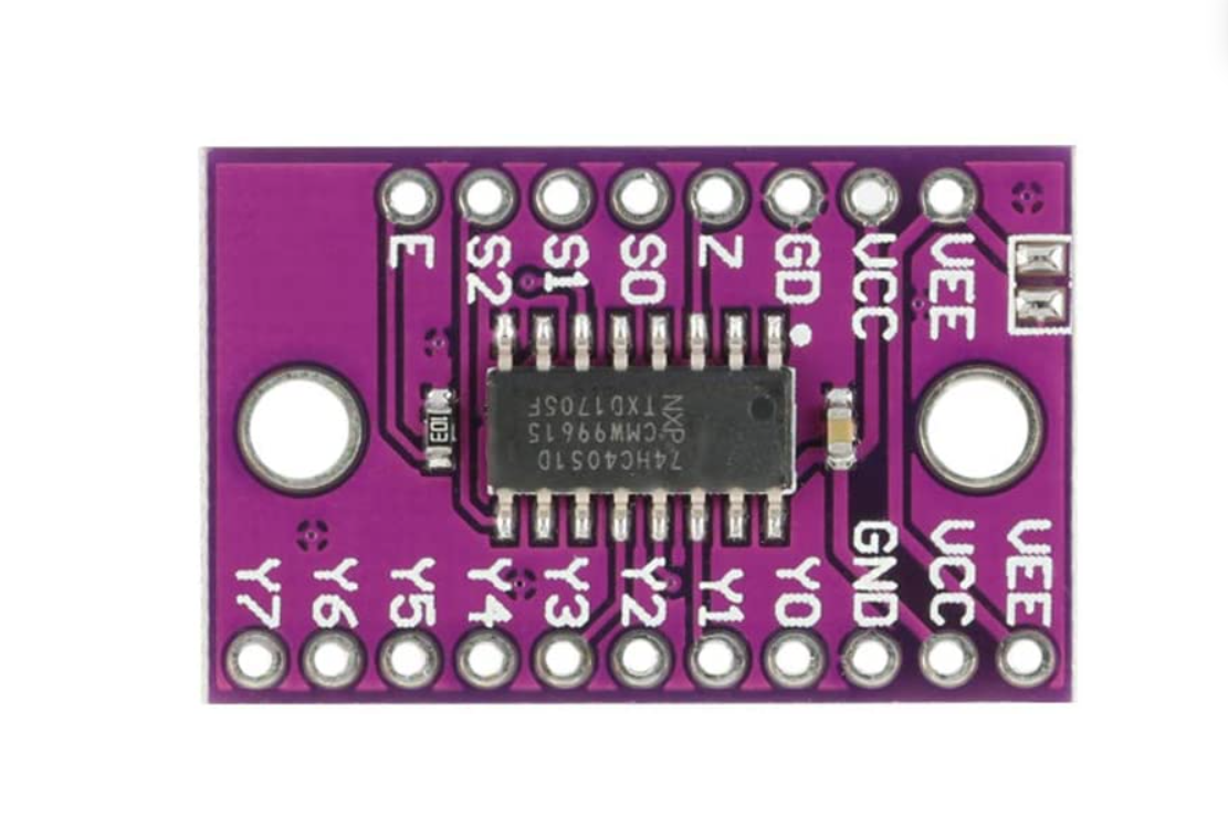
Pinout
Left Side
VEE — Negative power supply (can be left unconnected)
VCC — Module power supply, 5 V
GND — Ground
Z — Common input/output signal
S0–S2 — Digital select inputs to choose one of the 8 analog channels
E — Enable pin (active low; when HIGH, switches are off)
Right Side
VEE — Negative power supply (can be left unconnected)
VCC — Module power supply, 5 V
GND — Ground
Y0–Y7 — 8 analog inputs
Features
Wide analog input voltage range: −5 V to +5 V
Low ON resistance: 80 Ω typical at 4.5 V, 60 Ω typical at 9 V
Logic level translation — 5 V logic to ±5 V analog signals
Typical ‘break before make’ switching
Complies with JEDEC standard No. 7A
Inputs include clamp diodes for overvoltage protection